Directed Acyclic Graph Visualization Tool
Brief Instructions
This simple tool is designed to help with constructing, and visualizing, a directed acyclic graph (DAG), which is a directed graph with no directed cycles. That is, it consists of vertices and edges (also called arcs), with each edge directed from one vertex to another, such that following those directions will never form a closed loop.
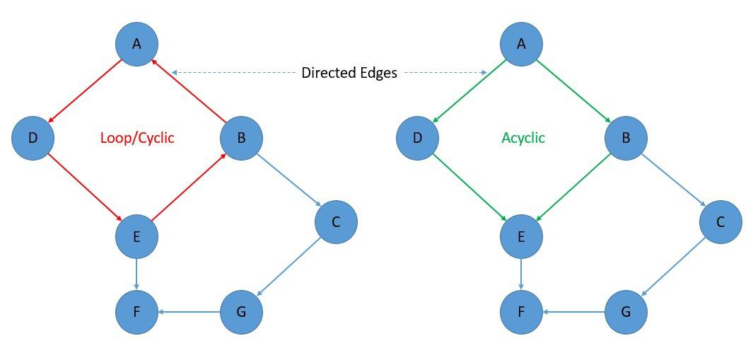
Diagram 1: Directed Cyclic and Acyclic Graphs
In our example, we use these types of diagrams to indicate the flow of radiological contaminants to receptors via various pathways. Alternatively, a graph may be represented as a square matrix with binary entries reflecting the binary adjacency relationship of the vertices of the graph. The Adjacency Matrix of the graph in Diagram 1 above is shown in Table 1 below.

Table 1: Adjacency Matrix of DAG in Diagram 1
For convenience, we have copied over the example drawing in the DAG Utility Tutorial. It is shown below.

Diagram 2: DAG Utility Example Drawing
The adjacency matrix corresponding to the example drawing in Diagram 2 is now shown in Table 2 below.
|
|
Label |
Title |
V1 |
V2 |
V3 |
V4 |
V5 |
V6 |
|
☒⇧⇩ |
V1 |
Site |
X |
þ |
|
|
|
|
|
☒⇧⇩ |
V2 |
Air |
|
X |
|
þ |
þ |
þ |
|
☒⇧⇩ |
V3 |
Receptors |
|
|
X |
|
|
|
|
☒⇧⇩ |
V4 |
Soil |
|
|
þ |
X |
|
|
|
☒⇧⇩ |
V5 |
Plant & Animal Products |
|
|
þ |
|
X |
|
|
☒⇧⇩ |
V6 |
Aquatic Plants & Animals |
|
|
þ |
|
|
X |
Table 2: DAG Utility Example Transaction Table
In our DAG utility, the adjacency matrix representation is used to construct DAGS, because it enables the user to perform algebraic computations with them. For example, a DAG can always be arranged in an "upper diagonal" form, with all selected checkboxes appearing above the main diagonal of the adjacency matrix as shown in Table 2.b below.
|
|
Label |
Title |
V1 |
V2 |
V4 |
V5 |
V6 |
V3 |
|
☒⇧⇩ |
V1 |
Site |
X |
þ |
|
|
|
|
|
☒⇧⇩ |
V2 |
Air |
|
X |
þ |
þ |
þ |
|
|
☒⇧⇩ |
V4 |
Soil |
|
|
X |
|
|
þ |
|
☒⇧⇩ |
V5 |
Plant & Animal Products |
|
|
|
X |
|
þ |
|
☒⇧⇩ |
V6 |
Aquatic Plants & Animals |
|
|
|
|
X |
þ |
|
☒⇧⇩ |
V3 |
Receptors |
|
|
|
|
|
X |
Table 2.b: DAG Utility Example Transaction Table in Upper Diagonal Form
This arrangement is automatically computed if you click the [Sort] button. This confirms that there are no loops in the diagram. If the user inadvertently attempts to create one, the action is prevented, and the error message “This graph is not acyclic!” is displayed.
Each row corresponds to a node in the graph. The [Add Row] button may be used to add new nodes. A node is characterized by its label and long-form title. The title is the text that will also appear in the diagram that represents the DAG.
It is possible to assign properties to nodes. To this end, click or tap the small triangle symbol in the upper right corner of the row's description. It is then possible to add, edit, or remove property-value pairs for that node. These property-value pairs are currently not used by the software, only stored.
Once multiple nodes are added to a DAG, the checkboxes in the right-hand side of the adjacency matrix come into play. Clicking a checkbox creates a directed connection from the node corresponding to the selected row to the node corresponding to the selected column, identified by the node label. The DAG diagram is updated accordingly. If the resulting graph becomes cyclic (i.e., if by clicking a checkbox, a circular path is introduced) an error message is shown.
The diagram is automatically adjusted to avoid, to the extent possible, overlapping connections, to ensure that the arrows can be read unambiguously. To find out which arrow corresponds to which checkbox, you can move the mouse cursor (on a desktop/laptop computer) to hover either over an edge in the graph or over a checkbox in the adjacency matrix. The corresponding matrix row, matrix column, and graph edge are highlighted.
You can change the order of nodes and thus alter the arrangement of the diagram by moving rows up or down in the adjacency matrix. This is accomplished using the up and down arrows in the corresponding row. A node can also be deleted, by clicking or tapping the delete symbol in the corresponding row.
A DAG may be saved on your device using the [Save] button. The saved file is in a proprietary format, with the DAG represented by a human/machine readable JSON object. The [Load] button allows you to load a previously saved DAG from your device.
There are several additional buttons in the application's top menu, allowing you to export a DAG. These include:
[CSV] - Export the adjacency matrix as a comma-separated file, suitable for loading into, e.g., Excel.
[Path] - Export path lengths or a path matrix for a given path length as a comma-separated file.
[SVG] - Export the DAG diagram as a scalable vector graphics (SVG) file.
[PNG] - Export the DAG diagram as a PNG image.
It is also possible to import an adjacency matrix in the form of a CSV file. To this end, use the [CSV] button in the Import section of the menu.
Finally, the [Help] button invokes the text you are presently reading, while the [Example] button loads a pre-generated DAG that corresponds to the one in our Tutorial.
[Close] - Clicking on this button after the help text file has been opened closes the help session.